Version 1 (custom machined, estimated cost $1500)
Front View, showing mirrors, eyepieces, biteboard, screw adjustments for IPD and short handles for adjustment of mirror angle (side mirrors). Looking through the two eye pieces, you're seeing a a pair of front-surface mirrors that reflect to the eyes whatever a second set of front surface mirrors (located at either side of the central unit) is aimed at (usually a video screen)
Close-up view of front of eyepiece, showing mirrors angled +/- 45 from the line of sight. These two front surface mirrors are fixed in place. Two more front surfaces mirrors are mounted at the ends of the eyepiece, one at the left and the other at the right (in this photo they appear as grey squares). The angle formed by those mirrors is adjustable (by turning the aluminum block on which they're mounted - see small "handle" on the left of the left-hand mirror).
View from the "back" of the stereoscope (the observer's head would be on the other side). The two mirrors are the ones glued to the aluminum blocks, whose angle is adjustable using the round "handles" which can be seen in this photo. The grey square in this photo is the back of the aluminum block to which the other pair of mirrors is glued. You can see the lens holders reflected in the mirrors.
For your amusement, here's a photo of a naive observer looking through the device:
Version 2 (commercially available components, estimated cost US $1300)
The head/chin rest system and the device for mounting the optical rail to this system (AccessoRack) are available from:
http://www.opt.uh.edu/uhcotech/headspot.html
The optical components are available from:
(4) Mirror Mount 112-0255
(4) Mirror Holder 112-0266
(4) Round Mirrors 033-0290
(4) Optical Carrier 146-1335
(1) Optical Rail 146-0390
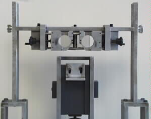
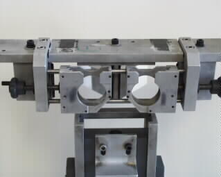
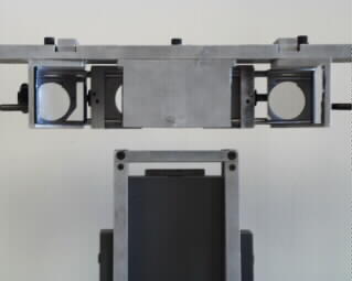
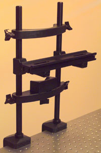
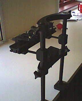
Current prices and detailed descriptions of the components are given on those websites. Below are three jpegs showing: the optical rail attached to the chin/head rest (left hand image), a closeup of the optics for achieving dichoptic stimulation (middle image) and the entire set-up with the optical components mounted on the rail (righthand image). The positions of the mirrors can be adjusted to achieve stable alignment of the two half-images; adjustments are made using small, precision screws that change the angles of the mirror mounts. The positions of the headrest, the optical rail and the chinrest can be adjusted independently on the two support posts that, themselves, clamp to a table.
 |
 |
 |
Let me amplify on a few points about the mirror stereoscope system shown above:
- the mirrors that the observer directly looks at (angled at 90 deg relative to one another in our setup) need only be large enough for the eye to get a full view of that eyeÕs stimulus, and that depends, among other things, on how close the eye is to the mirror. Closer the better (unless youÕre trying to monitor eye movements using a video eye tracker).
- we currently use our stereoscope with a single video monitor, which means each eyeÕs view can be no larger than half the width of the screen. That restricts the size of the stimuli you can use, of course, and if you want to work with large images or test at peripheral eccentricities, you may need to go to two video monitors (see below).
- some viewing situations require a ÒbaffleÓ extending from the midline of the stereoscope toward the screen; this can be a rigid piece of cardboard paint flat black (to minimize light reflection), and it serves to keep, say, the left eye from seeing any part of the right-half of the screen. the tendency for that to happen depends on your viewing distance and the size of the mirrors on the ÔarmsÕ of the stereoscope.
- in the past we have used a set-up using two matched video monitors, one for each eye, but that can introduce alignment and calibration problems.
- the mirrors must be aligned carefully by adjusting their angles around both the horizontal and vertical axes, and these can vary among individuals because of varying degrees of phoria. soÉ
- we use software to vary the x/y positions of the left stimulus and the right stimulus, independently within their two halves of the screen, so that theyÕre in alignment. To confirm alignment we implement, in software, a version of the cover/uncover test where the observer judges when the stimulus appears not to shift in position as the two images are shown briefly in alternation. We record the x/y coordinates for the left and right stimulus, and store that for use again for that observer. We do this for each person tested before each testing session, and this way the mirrors never get moved.
- another, altogether different option is to use liquid crystal shutter glasses (see, for example, this link), which allows full screen viewing with each eyeÕs image being presented on alternate video frames, synchronized to the frame presentation. This technique doesnÕt require the elaborate mirror alignment involved with mirrors, and observers seem to like it. However, it does entail on/off presentation of the stimuli to each eye (phase shifted so that one eyeÕs stimulus is ÒoffÓ while the other eyeÕs stimulus is ÒonÓ), and the frame rate of the goggles must be synchronized to the frame rate of the monitor (this is accomplished using an IR emitter and sensor). At bright luminance values, there can be a tendency to see faint flicker in the unit we purchased years ago, but the specs on the more recent models suggest this may be less of a problem now.
- a third possibility is the anaglyphic technique, which involves rendering your dichotic stimuli in two different colors (e.g., red/green) that can then be viewed through colored filters selected so that each lens passes only the image rendered in one color. Using MatLab code, itÕs easy to create anaglyphs, including movies, but this technique restricts you to the use of the two colors required by the lenses. Moreover, it can be difficult to get perfect color separation without resorting to relatively expensive, narrow-band filters (and narrow-band means dimmer images).
Below are three articles and one website that discuss techniques for achieving dichoptic stimulation.
Randolph Blake
01/25/2015
¥ Thompson, B., et al. (2008). "A dichoptic projection system for visual psychophysics in fMRI scanners." Journal of Neuroscience Methods 168: 71-75.
¥ Schurger, A. (2009). "A very inexpensive MRI-compatible method for dichoptic visual stimulation." Journal of Neuroscience Methods 177: 199-202.
¥ Carmel, D., et al. (2010). "How to create and use binocular rivalry." Journal of Visualized Experiments 45: e2030.
¥ http://www.funsci.com/fun3_en/stscp/stscp.htm